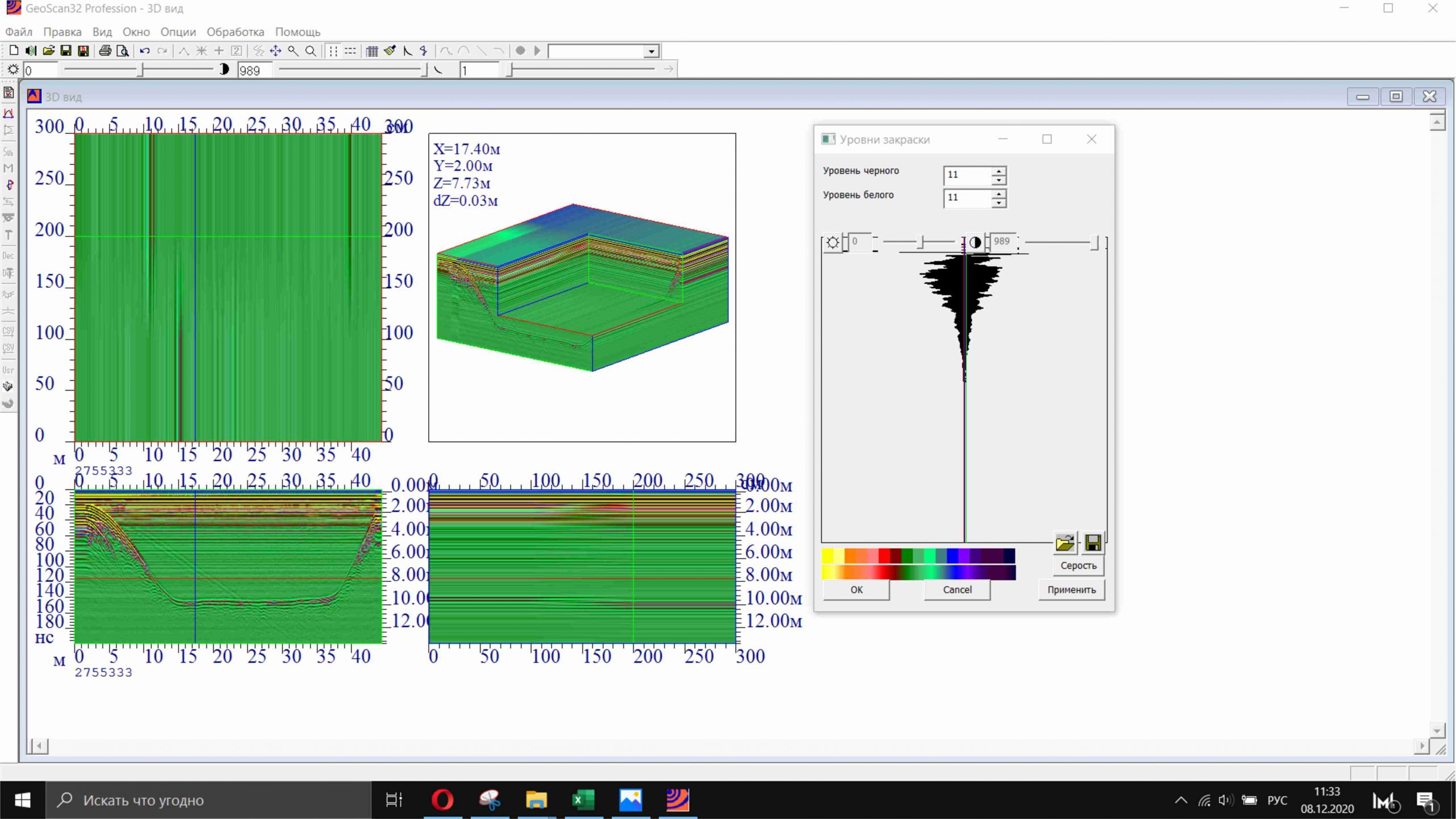
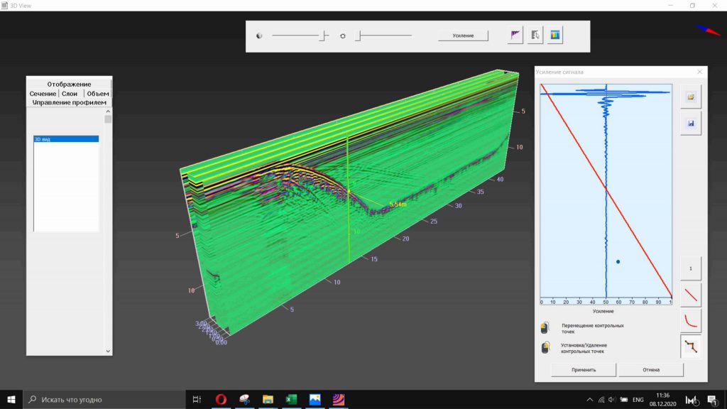
3D visualisation mode
A 3D image can take the form of intersecting planes or a cube.
In the 3D visualisation mode, users can change the gain profile, contrast, properties of the 3D block and redefine colouring.
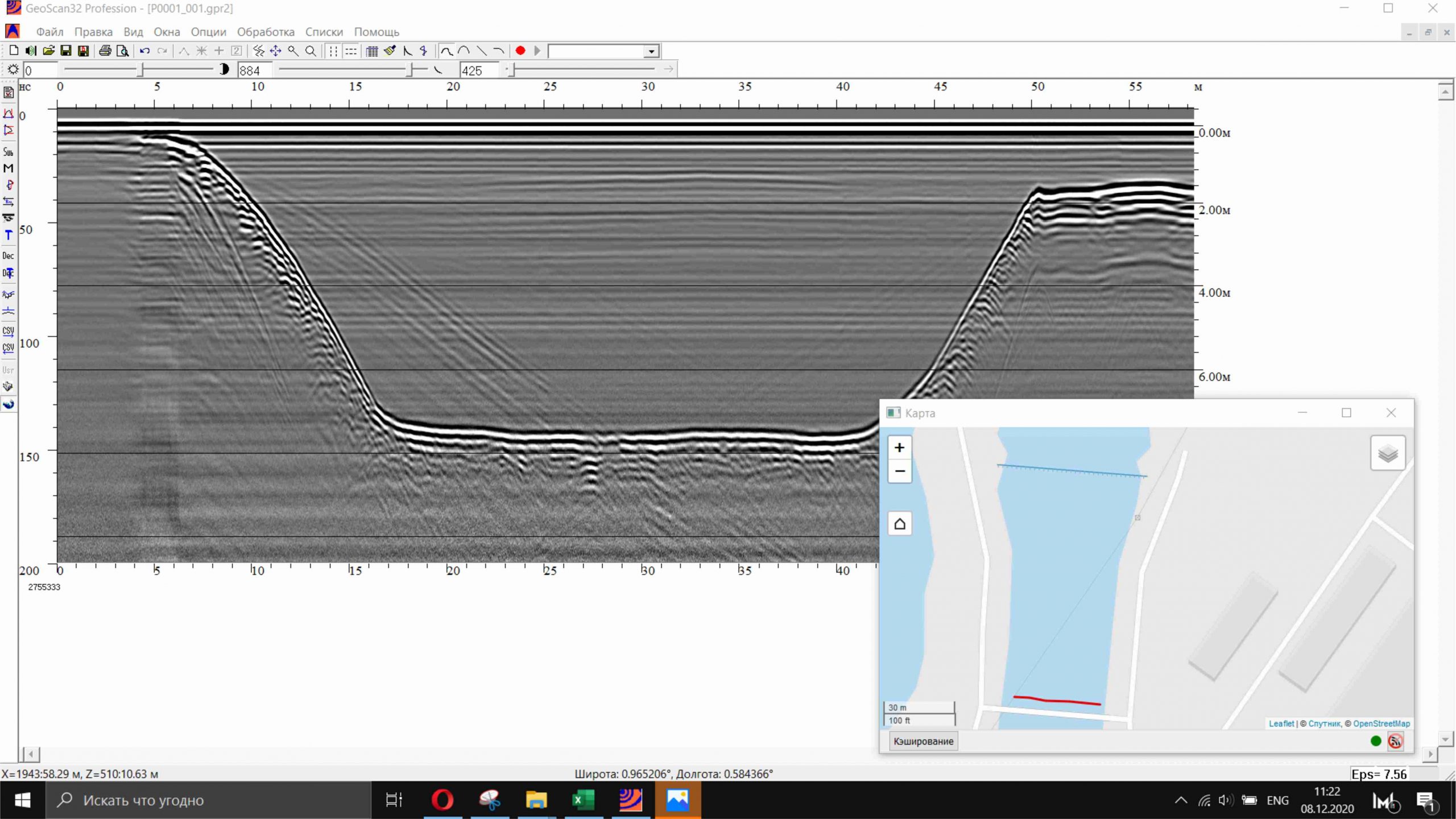
Working with the map
Working with the map consists in positioning the map in a given area, changing the scale and choosing the display type.
The red line on the map shows the route along which the GPR profile was scanned. Movement coordinates were obtained by GeoScan32 software using a GPS/GLONASS receiver. The coordinate data is stored in files of the same name as the GPR profile, but with the <.log> or <.gps> extension, which are automatically created by the GeoScan32 program when scanning using a GPS/GLONASS receiver.
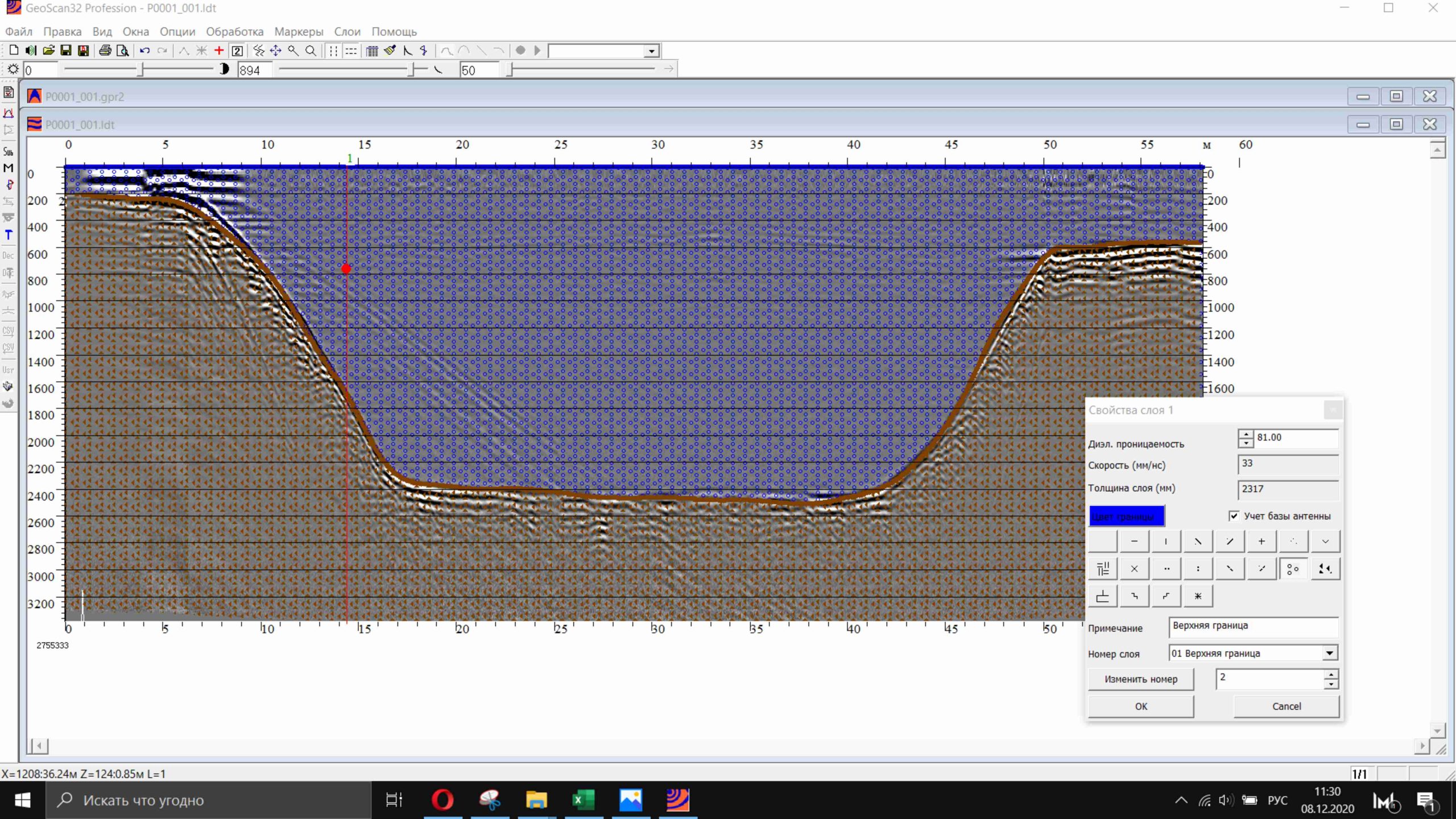
Layered interpretation of profiles
GPR surveys often reveal fairly extended and homogeneous zones. They can be represented as soil layers with individual values of the propagation velocity of an electromagnetic wave, which is determined by the dielectric constant of the medium.
Having determined the permittivity at some point of the layer, it can be applied to the entire layer. In this case, it becomes possible to bring the GPR profile image in line with its geometric dimensions. This can be very useful in road construction and many other fields.
Therefore, GeoScan32 software provides a separate mode that allows an operator to draw layers on the profile, change their properties and export layer data for further processing in Autocad or similar programs.
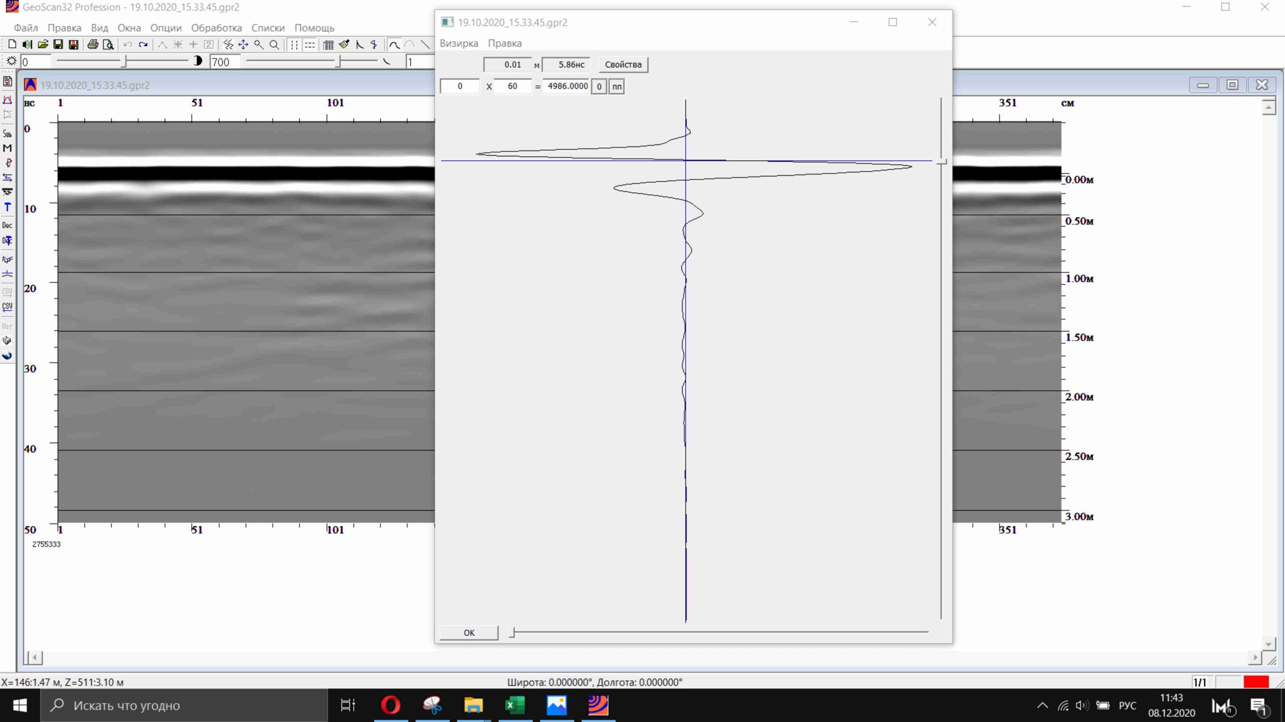
Setting the depth scale zero
To accurately determine the depth of occurrence of objects, it is necessary to correctly establish the reference point of the depth, i.e. “attach” zero to the surface of the medium. Often this happens automatically due to the fact that the amplitude threshold is set (see section 5.2). Still, sometimes it has to be adjusted. Before measuring the depth of an object or layer, we recommend that you make sure that the zero is set correctly.
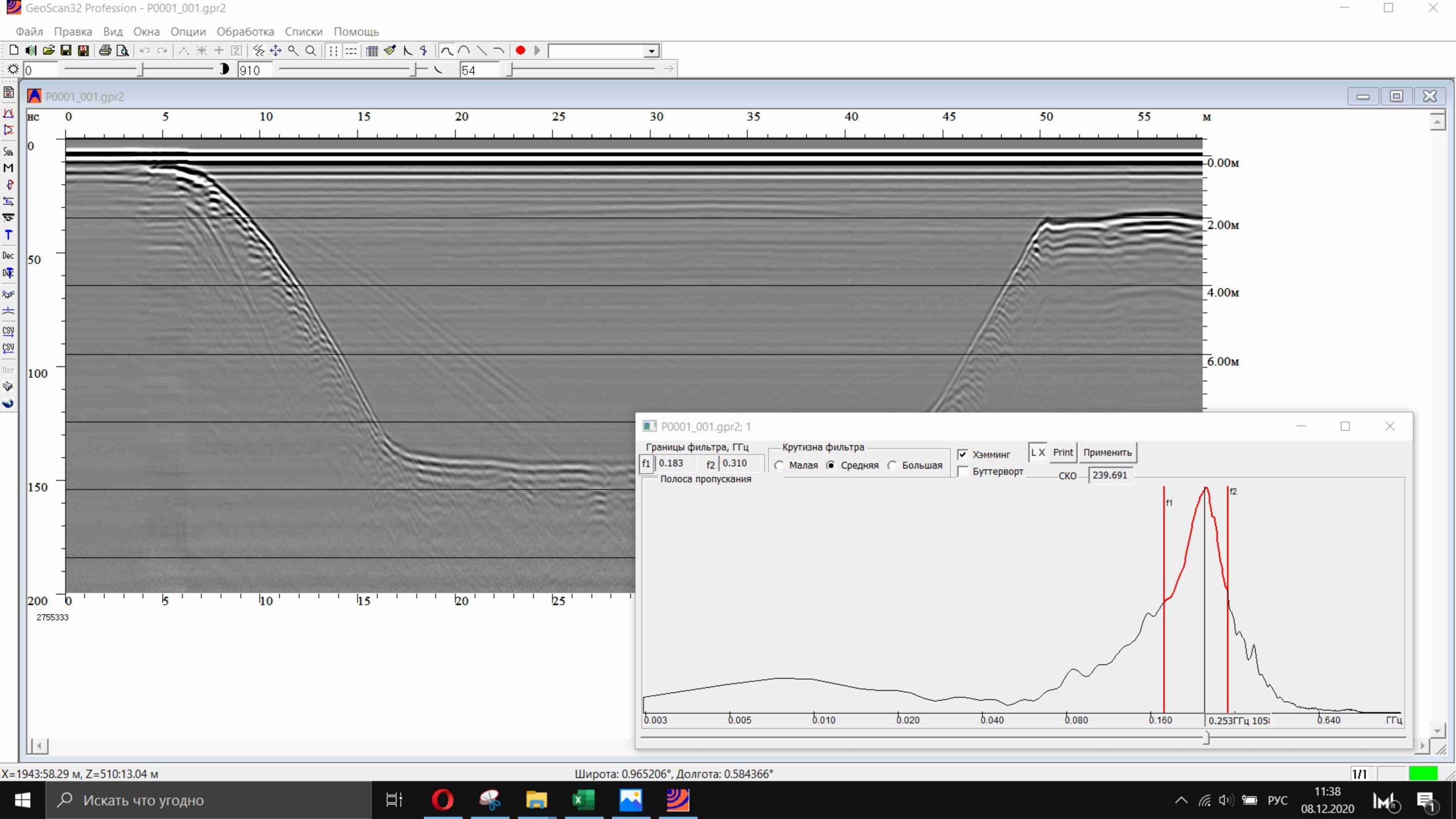
Spectrum